|
| CH-47F Chinook helicopter Photographs |
| Take a photographic tour of the new Chinook helicopter - the F model. This is not a rebuild of the airframes that once flew over the skies of Vietnam. This is a powerful, brand new and very advanced computerized flying machine. |
|
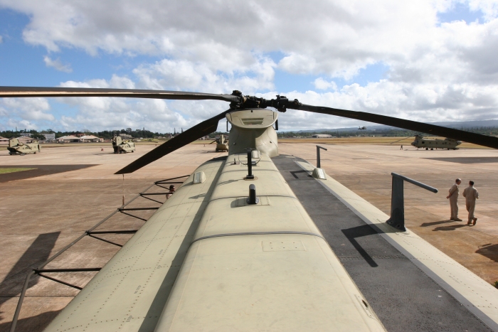
| The top of the CH-47F looking forward from the Combining Transmission area. Visible on the Tunnel Covers are the 2 GPS Antennas and the new Satellite Communication (SATCOM) System Antenna (looks like an eggbeater). Also visible in the photograph is the Forward Pylon, on top of which sits the Forward Rotor System, various Antennas for radio communication and the Electroluminescent Formation Lights (3 each). Click-N-Go Here to view a larger image. |
|
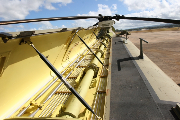
| The top of the CH-47F looking forward from the Combining Transmission area with the Tunnel Covers open. The Synchonizing Drive Shafts (aka Sync Shafts), shafts 2 thru 6 of the 7 each forward of the Combining transmission, are visible here. These shafts keep the Forward and Aft Rotor Systems in phase by locking the Forward, Combining and Aft Transmissions together. When one transmission turns, so will the others. While in phase, the Rotor Blades from each head do not touch or overlap each other. If they touch in flight the aircraft will disintegrate within seconds. Click-N-Go Here to view a larger image. |
|
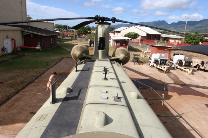
| The top of the CH-47F looking aft towards the Aft Pylon. Visible in the photograph are the two Main engines and the Aft Pylon, on top of which sits the Aft Rotor System. The black stripped area is the walkway for personnel to move about the top of the aircraft. Click-N-Go Here to view a larger image. |
|
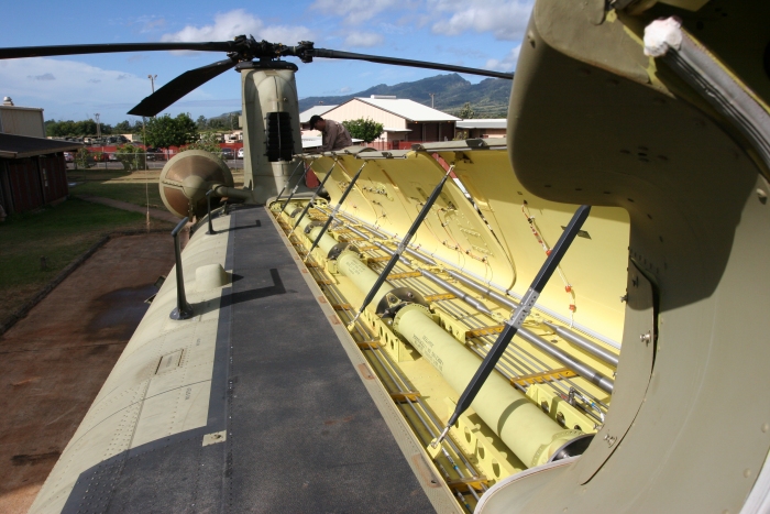
| The top of the CH-47F, with the Tunnel Covers open, looking aft towards the Aft Pylon. The bright, shiny, silver colored twin sets of tubes to the left of the yellow Sync Shafts (on the right in the photo) are the Flight Control Push-Pull Tubes that connect the cockpit flight controls to the Aft Rotor System. Click-N-Go Here to view a larger image. |
|
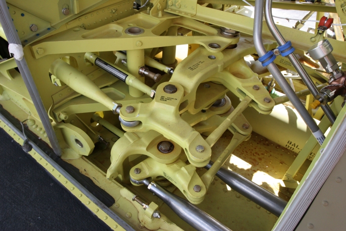
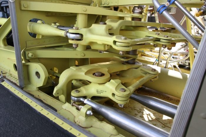
| The Second Stage Mixing Unit for the H-47 Flight Control System. Does it look complicated? Yes, it is. However, "works good - last long time". Click-N-Go Here to view a larger image. |
|
| The Second Stage Mixing Unit for the H-47 Flight Control System. It's located in the aft portion of the Forward Pylon. Visible in the photograph is the # 1 Sync Shaft. Click-N-Go Here to view a larger image. |
|
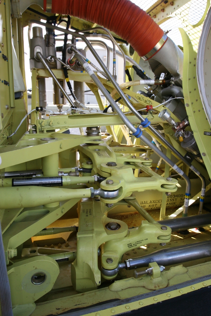
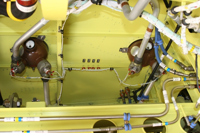
| The Second Stage Mixing Unit for the H-47 Flight Control System. Also visible in the photograph is the Brake Accumulator, # 1 Flight Control Hydraulic System Reservoir, and the # 1 Flight Control Hydraulic Pressure Control Module. Click-N-Go Here to view a larger image. |
|
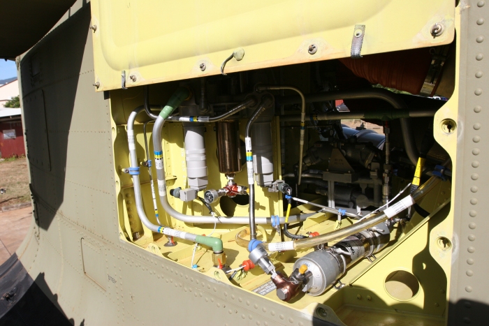
| The right hand Aft Hydraulics Compartment for the H-47 Chinook helicopter. Visible in the photograph is the Bootstrap Accumulator for the Utility Hydraulics System, the # 2 Flight Control Hydraulic System Power Control Module, and the # 2 Power Transfer Unit. Click-N-Go Here to view a larger image. |
|
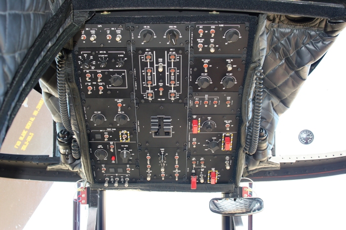
| The Overhead Panel in the CH-47F Chinook helicopter. Located on this panel are the various lighting control switches and rheostats, auxiliary power unit control switches, generator control switches, heater control switches, troop alarm switches, engine start and speed control (engine condition levers or ECLs), fuel pump control switches, winch and cargo Hook controls, and the flight boost hydraulic control switches. Just a whole bunch of switches... Click-N-Go Here to view a larger image. |
|
| The Engine Fire Bottles of the CH-47F Chinook helicopter. Either Bottle (or both) can be discharged into either or both engines to extinguish a fire. The activation of the Fire Bottles is controlled from the cockpit. This view is from the inside of the Main Cabin area, right side, looking up above the Number 7 and 8 Sync Shafts. Click-N-Go Here to view a larger image. Click-N-Go Here to view a larger version of this image with the components labeled. |
|
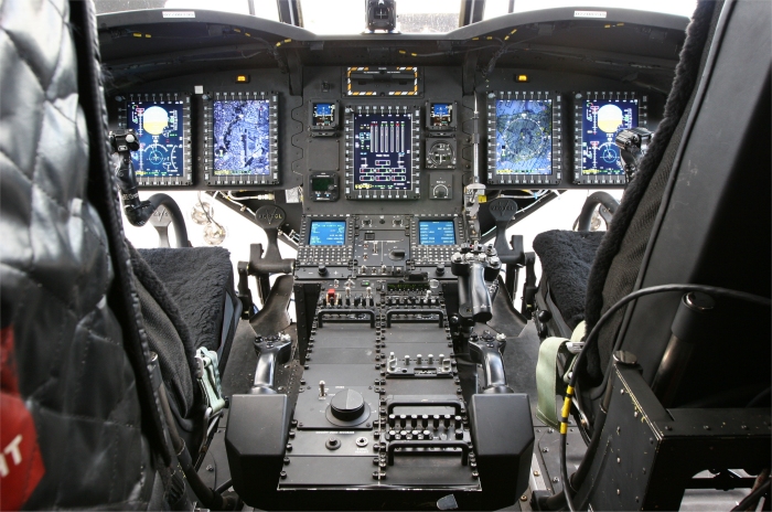
| The advanced cockpit of the CH-47F Chinook helicopter. On the dashboard are five Multi-Function Displays (MFD) that can be set up in a variety of ways allowing the pilot to monitor engines and transmission indications, navigate via a moving map display that integrates dual Global Positioning System (GPS) and Inertial Navigation (INU) computers, and input a completely automated flight plan, amongst many other features. The computerized data can be coupled directly to the flight controls allowing hands-off flight from takeoff to landing at a hover anywhere in the world. Click-N-Go Here to view a larger image. |
|
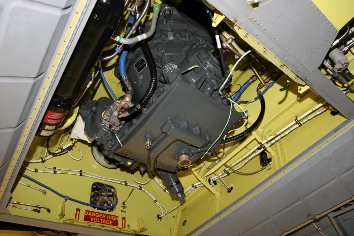
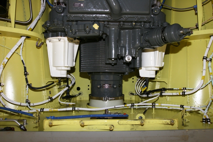
| The Aft Transmission of the CH-47F Chinook helicopter. Forward is to the top right in the photograph. To the left (in this image) of the transmission is the 375 inch accumulator (long black cylinder) that provides hydraulic pressure required to start the Auxiliary Power Unit (APU). Mounted on the transmission are two hydraulic pumps. One is the Number Two Flight Control Hydraulic Pump. The other, which is visible in the image (silver looking) is the Utility Hydraulics System Pump. Aft of the transmission is where the APU is mounted. One can see the APU Motor-Pump sticking through the bulkhead above the danger sign. Also visible is the Thomas Coupling, often refered to as the Flexible Adapter Plates or Flex Pack (the correct term is Thomas Coupling). Click-N-Go Here to view a larger image. Click-N-Go Here to view a larger version of this image with the components labeled. |
|
| The Main Generators mounted on the Aft Transmission of the CH-47F Chinook helicopter. Forward is at the top in this photograph. The generators are 40 KVA units. A single generator adequately supplies all of the electrical power requirements of the helicopter with plenty of power to spare. Typically, only 15 percent load capacity is placed on a single generator during normal operations. A second generator is mounted to provide redundancy should either fail. The Number One Generator is on the right in this image and Number Two is on the left. The gray cylinder forward of the Number Two Generator is the Aft Transmission Oil Filter. Click-N-Go Here to view a larger image. Click-N-Go Here to view a larger version of this image with the components labeled. |
 |
|
| Comments or Questions ? |  |
Email the Webmaster. |
|
|