|
| The Height Velocity Diagram Explained |
|
| Sheet 1 of the H-47 Chinook helicopter Height Velocity Diagram. |
| Having a challenge understanding how to use the H-47 Chinook helicopter Height-Velocity Diagram? You are not alone. Many folks have looked at this diagram over the years and felt confused. There are no instructions in the Dash 10 on how to break the code. |
| To begin with, Click-N-Go Here to down the complete set of diagrams. The file is in .pdf format. |
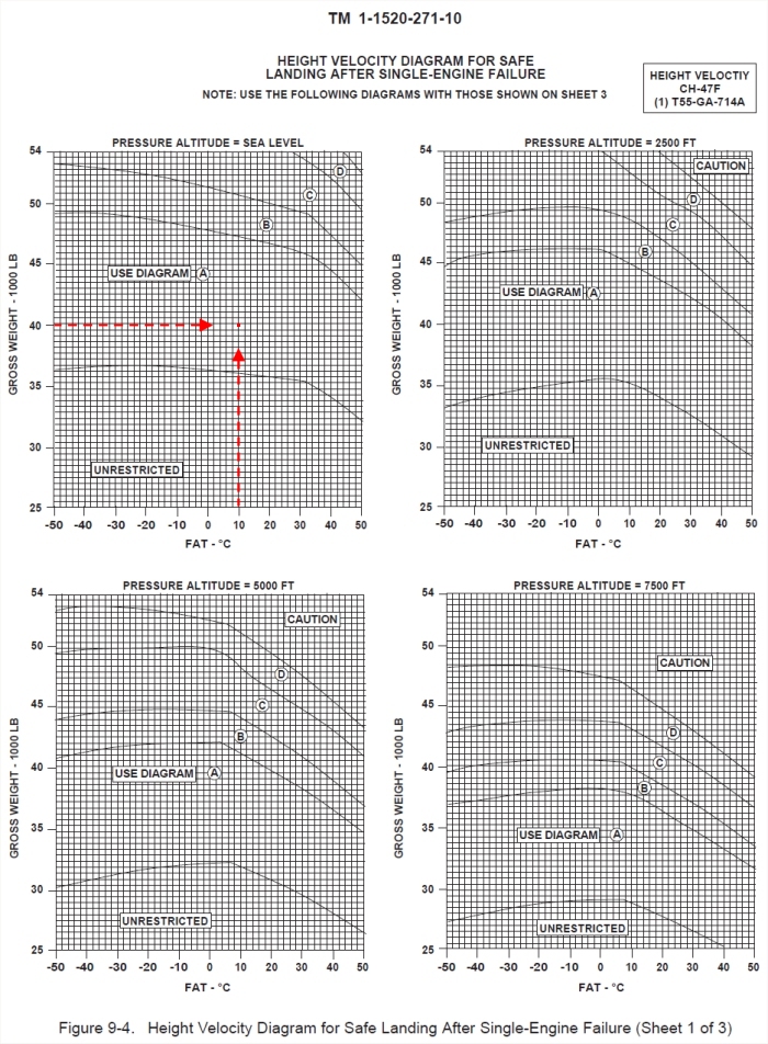
| Sheets 1 and 2 allow one to determine the correct diagram area to use on Sheet 3 in order to ascertain the AVOID, SAFE, and CAUTION areas in which to operate the aircraft in the event of a single engine failure. |
| On Sheet 1 or 2, one must know the current Pressure Altitude (PA), Gross Weight (GW), and Outside Air Temperature (OAT). |
| As an example on how to use the Diagrams, let's use Sea Level PA, 40,000 pounds GW and 10° Celcius (OAT). |
| We can see that Sheet 1 of the Diagrams show this operating condition (Sea Level PA) at the upper left of the page (see image at top of this page). |
| Enter the Sea Level PA Chart at Gross Weight and slide right until that line intersects with the temperature line of 10 degrees (the red dot on the image at the top of the page). |
| The red dot falls in the area that is marked USE DIAGRAM A. Note that information and move to Sheet 3 (see below). |
|
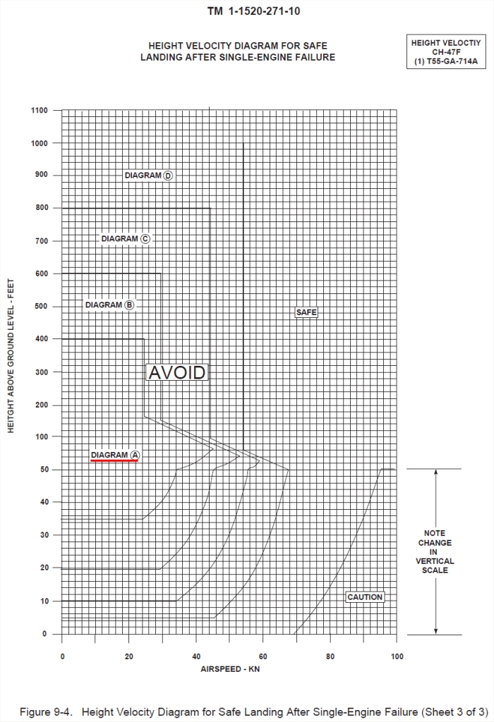
| Identify the area on Sheet 3 that is depicted as DIAGRAM A (underlined in red in this example, but not in the Dash 10). Note that the entire area covered by the Diagram A in enclosed by a thin black border. |
| On Sheet 3, Height above Ground Level (AGL) is the vertical scale on the left side of the chart. Airspeed is the horizonal scale on the chart along the bottom. |
| When analyzing the information available from the chart, ANY combination of altitude and airspeed that falls within the DIAGRAM A area is to be AVOIDED. |
| ANY combination of height and airspeed that falls to the right (or outside at top or bottom) of the area bordered by DIAGRAM A is SAFE up to, but not including, the area marked CAUTION. |
| The same procedures apply if one is directed to use DIAGRAMS B, C or D. |
| In this case, ANY height and airspeed combination to the RIGHT (or outside at top or bottom) of DIAGRAMS A, B, C or D is SAFE up to, but not including, the CAUTION area. |
| ANY height and airspeed combination to the LEFT and INSIDE of DIAGRAMS A, B, C or D is to be AVOIDED. |
| The AVOID areas indicate those combinations of Height and Velocity that WILL NOT allow for sufficient manuvering capability to safely land after one engine fails. Chances are one would break the aircraft and/or injure/kill the crew. |
| The CAUTION area indicates those combinations of Height and Velocity that MAY allow for sufficient manuvering capability to safely land after one engine fails. A properly skilled pilot MIGHT save the day. |
| Related Information |
| 87-00102 |
 |
|
| Comments or Questions ? |  |
Email the Webmaster. |
|