|
| The Rotor Blade |
|
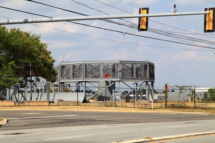
| August 2015: The Whirl Tower at the Boeing Factory in Ridley Park, Pennsylvania. Rotor Blades are mounted on a head and then spun at normal operating speed (225 RPM) where data could then be collected and adjustments made to enhance their flying characteristics. There are actually two whirl towers at this location, one is hidden behind the tree on the left. Click-N-Go Here to view a larger version. |
|
| In a Chinook helicopter, the structure making flight possible is the airfoil - a surfaced body that responds to relative motion between itself and the air with a useful, dynamic reaction known as lift. The term airfoil, as applied to the CH-47, refers to the rotary wing, and more specifically means the curvature, or camber, of the blade. |
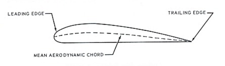
| As illustrated below, an airfoil section may be defined as the cross section of any surface producing lift. As the diagram indicates, the thick end of the section is known as the leading edge. The small tapering end is the trailing edge. The distance between the leading edge and the trailing edge is known as the chord of the airfoil. |
|
| The rotary wing blade in a CH-47 is asymmetrical, that is it has a curvature that changes along the entire length of the chord. If the blade were symmetrical, then the chord line would be a straight line from the leading to the trailing edges. Since the curvature changes constantly in the CH-47 rotor blade, the result is that the chord of the blade also changes. When computing the chord line of this type of blade, an average or mean aerodynamic chord (MAC) becomes apparent as shown above. |
| When a blade (airfoil) is moved through the air, a stream of air flows over and under it. The blade is designed so that the flow of air will be smooth and will conform to the shape of the moving blade. If the blade is set at the proper angle and made to move fast enough, the airflow will support the weight of the blade. This is the nature of the action that enables rotary wings to furnish enough lift to sustain the helicopter in flight. |
|
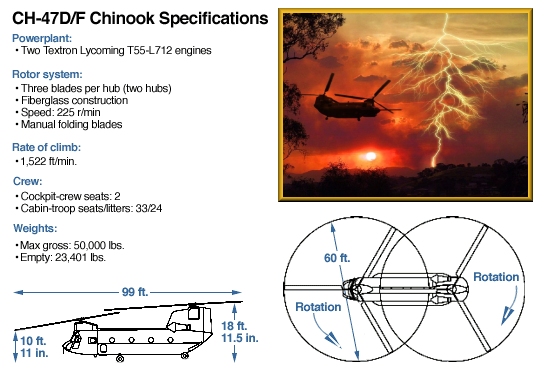
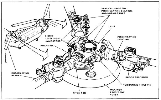
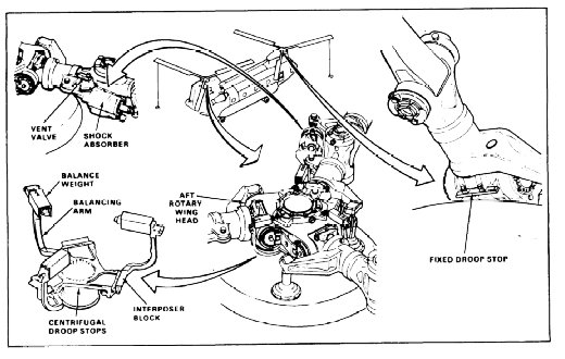
| Lift, in a Chinook helicopter, is produced by a rotor system consisting of two fully articulated counter-rotating rotors. Each rotor has three fiberglass blades. The forward rotor is driven by the forward transmission through the rotor drive train. The aft rotor is driven by the aft transmission through a vertical drive shaft. The rotor head consists of a hub connected to three pitch-varying shafts by three horizontal hinge pins. These pins permit blade flapping, which is the up and down movement of the rotor blade. Stops on the top and the bottom of the hub limit the blade flapping motion. The aft rotor head is equipped with centrifugal droop stops which provide increased blade flapping angle for ground and flight operation. Covers may be installed on the centrifugal droop stop operating mechanism. The covers prevent ice accumulation on the mechanism and ensure proper droop stop operation following flight in icing conditions. |
|
| Mounted coaxially over the pitch-varying shafts are pitch-varying housings to which the blades are attached by vertical hinge pins. These pins permit blade leading and lagging. Each pitch-varying shaft is connected to the pitch-varying housing by a laminated tie bar assembly. The high tensile strength and low torsional stiffness of the tie bar retains the blade against centrifugal force and allows blade pitch changes about the pitch axis. Blade pitch changes are accomplished by three pitch-varying links connected from the rotating ring of the swashplate to the pitch-varying housing on each rotor blade. Cyclic pitch changes are accomplished by tilting the swashplate. Collective pitch changes are accomplished by vertical movement of the swashplate. Combined collective and cyclic pitch changes result from combined control inputs by the pilot. A direct-action shock absorber is attached to the blade and to the pitch-varying housing. When the inboard end of the shock absorber is disconnected, the blade can be folded in either direction about the vertical hinge pin. |
|
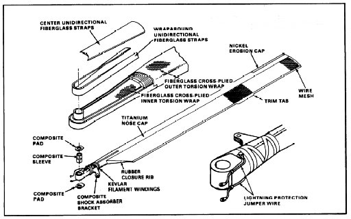
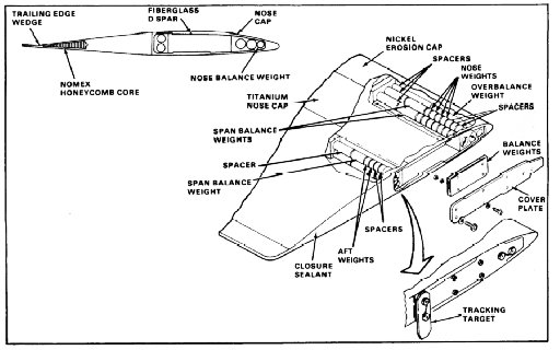
| Each rotor blade consists of a D-shaped fiberglass spar assembly and a Nomex fairing assembly bonded to the spar. The blade chord (width) is 32 inches, and the shape of the airfoil is asymmetrical (the upper and lower surfaces are of different shape). From root to tip, the blade has a 12 degree negative twist to provide for a greater control range throughout the entire flight envelope. A titanium nose cap is bonded to the leading edge of the spar. A nickel erosion cap is bonded to the blade along the outer 54 inches of leading edge. This cap protects the part of the blade most vulnerable to erosion. The fairing assembly is bonded to the trailing edge of the spar. These fairings are constructed of a Nomex honeycomb core covered with a fiberglass skin. Wire mesh screens are embedded in the fiberglass skin at the tip and the trim tab. The wire mesh screens provide an electrical path to the rotor hub from the metal trim tab and tip for lightning protection. Also, to provide lightning protection, each blade has two lightning protection cables and two straps. The cables and straps complete the path from the wire mesh to the rotor head. Balance and tracking weights are installed in the tip of spar and fairing assembly. The tracking weights are removable and are used for blade track and balance. |
|
|
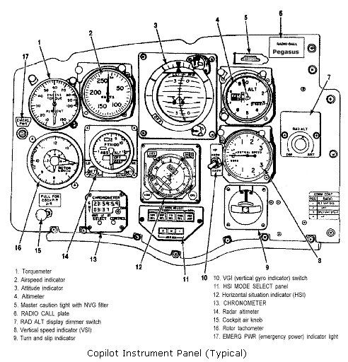
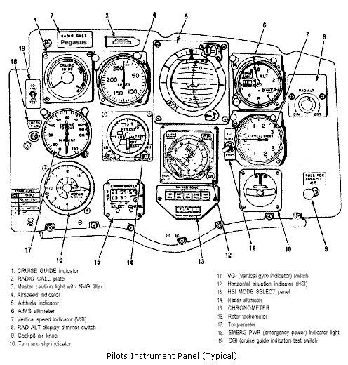
| Two rotor tachometers, one mounted on the copilot instrument panel (above), the other mounted on the pilot instrument panel (below), indicate percent of rotor revolutions per minute (RRPM). A small needle on the tachometer indicates percent RPM from 0 to 60. The large needle indicates percent RPM from 60 to 130. The helicopter is operated at 100 percent rotor RPM during flight. 100 percent rotor rpm equates to 225 revolutions per minute. The RRPM sense signal is supplied by the alternating current (AC) Generators. Both the No. 1 and No. 2 Generators are mounted on the aft transmission and operate at a speed that is proportional to that of the entire drive train. Thus, any change in rotor rpm is reflected in the speed of the gears within the aft transmission, and ultimately in the generators themselves. Permanent magnet generators are located in each generator. These type of generators require no external power to operate and produce a signal useful to determine rotor rpm simply by being operated (turning). This signal (electrical impulse) is routed to the cockpit and displayed on the rotor tachometer gauges. Generator No. 1 supplies the copilot indicator and generator No. 2 supplies the pilot indicator. Power to operate the indicators is supplied by the direct current (DC) essential bus through the ROTOR TACH circuit breaker on the No. 1 and No. 2 power distribution panel (PDP). |
|
| Related Sites |
| Droop Stop Failure |
| Rotor Blade Failure |
 |
|
| Comments or Questions ? |  |
Email the Webmaster. |
|