|
| The CH-47 T55-L-712 Chinook Engine |
|
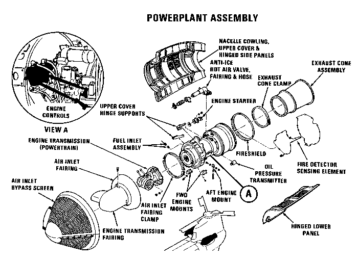
| A drawing showing the various placement of items on the Lycoming T55-L-712 engine used on the CH-47C and CH-47D Chinook helicopters. Click-N-Go Here to view a larger image. |
| Introduction |
| For the U. S. Army, this engine was used on CH-47C and CH-47D helicopters from the mid 1980s through the late 2000s. It was also used on some models in some countries other than the United States. |
| The powerplant system includes main engine units, engine drive accessories, air induction system, exhaust systems, cooling systems, fuel systems, system controls, and starting system. The main engines are Lycoming Model T55-L-712 gas turbines. One is installed on each side of the aft fuselage on the exterior of the helicopter. The engine will include electric torquemeter system components and a gas producer tachometer generator. The air induction system consists of an inlet at the forward end of the engine assembly. An exhaust duct is connected, by means of a quick-disconnect clamp, to the rear of the engine. The engine lubrication system is entirely selfcontained. Fuel is supplied to the engines from the main tanks. Engine control is by means of the Nl and N2 systems. The engine includes a hydraulic starter for starting the engine. Cooling of the engine is through openings in the nacelle cowling. The maximum rated shaft horsepower of the engine is 4600. The engine wiring, fuel, and hydraulic components are connected to the airframe at a quick-disconnect shelf below each engine. This allows quick change-out of the complete engine package. |
| Description |
| The AVCO Lycoming T55-L-712 gas turbine engine is a direct-drive shaft turbine engine with a two-stage, free-type power turbine, an external annular combustor, and a two-stage gas producer turbine that drives a combination axial centrifugal compressor. The power turbine shaft, positioned coaxially within the compressor shaft, directly drives the output shaft located at the compressor inlet end of the engine. The six major sections of these engines are air inlet, accessory drive, compressor, diffuser and combustor, gas producer, and power turbine and exhaust. |
| All sections are designed to include an annular flow path for the air or hot gases, are structurally interdependent, support all internal rotating systems, and provide attaching capabilities for engine-required external components and airframe accessories. |
| Each engine is made up of two basic sections: a gas producer section and a power turbine section. These two sections are not mechanically connected, but the hot gases, produced by combustion, flow from one unit to the other. During engine start, air enters the engine inlet and.is compressed as it passes through various stages of the compressor rotor. The compressed air passes through a diffuser and into the combustion chamber, where it is mixed with starting fuel and ignited. |
| After the engine is started, it continues to operate on metered main fuel which is supplied to the airblast nozzles. Hot expanding gases leave the combustion chamber and drive a compressor turbine which, in turn, drives the compressor rotor. Remaining energy from the combustion gases drives the power turbine which, in turn, drives the power output shaft, which drives the engine transmission. |
| Maintenance, removal, replacement. or quick-change of either engine is facilitated by the location of the nacelles, the design of the engine mounts, and the use of quick-disconnect couplings on all lines which lead to the aircraft structure. Each engine is secured by three mounts: two forward and one aft. Normal access for maintenance is gained through hinged access doors on either side of the engine covers. |
| Engine Cross Section |
|
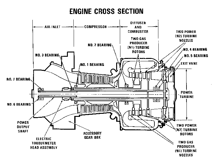
| The Lycoming T55-L-712 Engine Cross Section showing the major separate areas of the powerplant. Click-N-Go Here to view a larger image. |
| The T55-l-712 engine is made up of four sections. The sections are: air inlet and accessory gearbox, compressor, diffuser and combustor. Running through the center of the engine are the N1 and N2 drive shafts. Mounted on the N1 shaft are the two gas producer power turbine rotors, centrifugal compressor and axial compressor. The No. 1 and No. 2 main bearings support the N1 drive shaft. The N2 drive shaft has two power turbine rotors mounted on the aft end in the combustor area, and the power output shaft is splined into the forward end of the N2 drive shaft. The No. 3, 4, and 5 bearings support the N2 drive shaft and the aft portion of the power output shaft. The No. 6 and 7 bearings support the front or output end of the power output shaft. |
| Additional Drawings |
|
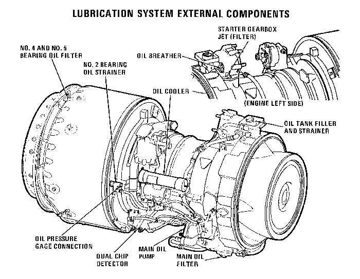
| The Lycoming T55-L-712 Engine Lubrication System External Components. Click-N-Go Here to view a larger image. |
|
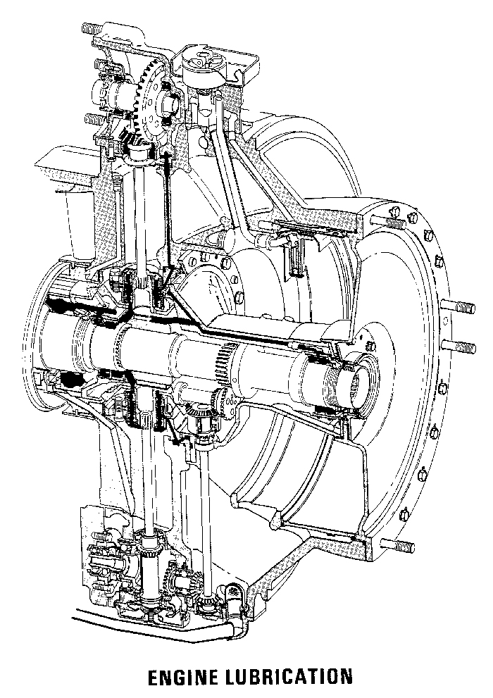
| A drawing showing the internal lubrication of the forward section of the Lycoming T55-L-712 engine used on the CH-47C and CH-47D Chinook helicopters. Click-N-Go Here to view a larger image. |
| Related Sites |
| Power Developed by Various Engine Models |
| Boeing Service Bulletin 145-76-1004 (FADEC) |
| Lycoming Engine Development, June 1963 |
 |
|
| Comments or Questions ? |  |
Email the Webmaster. |
|