| Camp Bondsteel, Serbia, Accident Photographs |
| The Day After The Day After Continued |
|
| 89-00138 |
| Camp Bondsteel, Serbia, Accident Photographs |
| The Day After The Day After Continued |
|
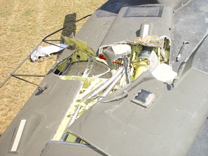
| July 2002: With the droop stop on the aft green horizontal hinge pin housing failing to engage, the aft green rotor blade struck the number one and number two tunnel covers causing severe damage to the flight controls and other components housed within. Click-N-Go Here to view a larger version of this image. |
|
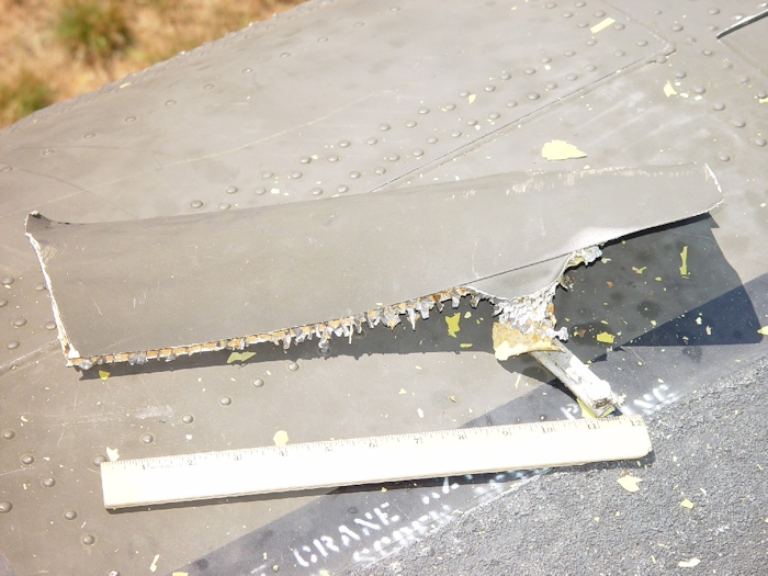
| July 2002: Debris created as a result of the blade to fuselage contact was scattered around the crash site. Here a piece is found on top of the aircraft near the forward pylon above the main cabin door. Click-N-Go Here to view a larger version of this image. |
|
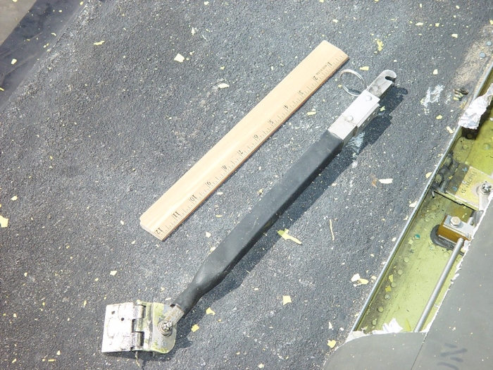
| July 2002: Debris created as a result of the blade to fuselage contact was scattered around the crash site. Here half of a tunnel cover support strut is found on top of the aircraft near the forward pylon. Click-N-Go Here to view a larger version of this image. |
|
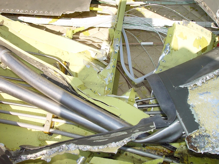
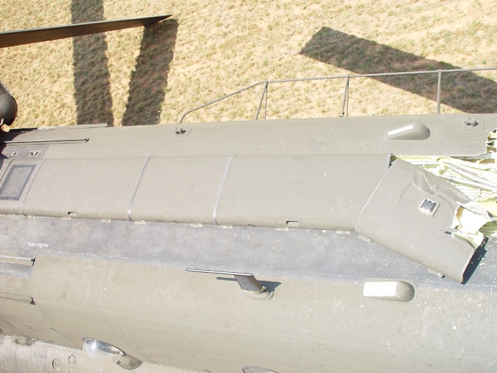
| July 2002: When the aft green blade struck the fuselage it was moving right to left in this photograph. As contact was made the blade ripped through skin and dug in, severely damaging the flight control tubes leading to the aft rotor system and displacing the number one and two tunnel covers. At this point, the aircraft was no longer flyable. Click-N-Go Here to view a larger version of this image. |
|
| July 2002: When the aft green blade struck the fuselage it was moving left to right in this photograph. As contact was made the blade ripped through skin and dug in, severely damaging the flight control tubes leading to the aft rotor system and displacing the number one and two tunnel covers. At this point, the aircraft was no longer flyable. Click-N-Go Here to view a larger version of this image. |
|
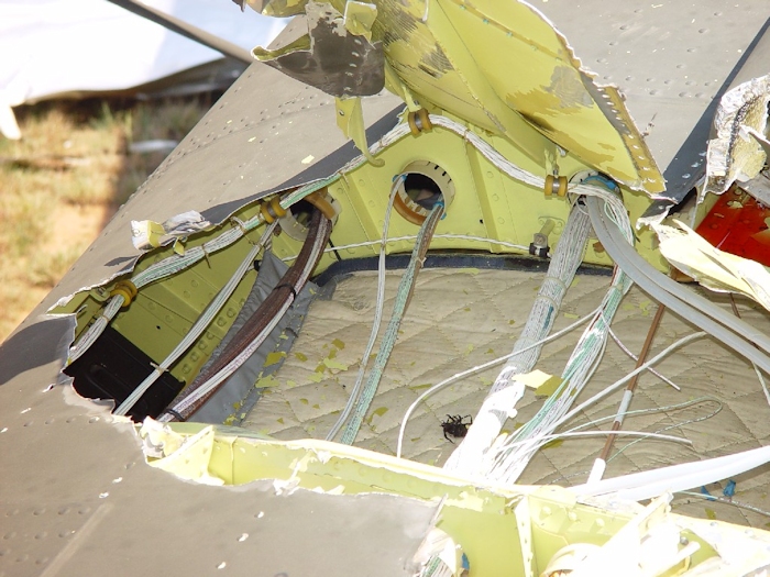
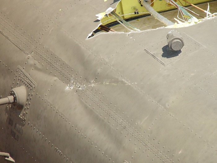
| July 2002: In a close-up view of one of the damaged area, it can be seen that the fuselage skin of the Chinook helicopter, although strong, is not very thick. Some wires were cut as the blade penetrated the area and apparently, at some point, a large insect was a casualty as well. Click-N-Go Here to view a larger version of this image. |
|
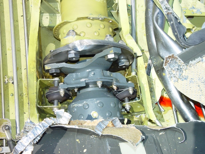
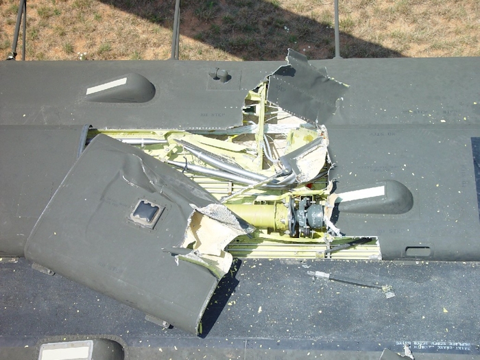
| July 2002: The Flex Pack (Thomas Coupling) on the drive shaft took a direct hit from the blade as evidenced by the large dent. The drive shafts (synchronizing or just sync shafts) allow the drive train to flex during flight operations. There are seven individual sync shafts in the forward section of the helicopter and two in the rear. As the helicopter flies, the fuselage twists and turns. Without the flex packs to absorb this movement, the drive train would be too rigid and it would fail. Click-N-Go Here to view a larger version of this image. |
|
| July 2002: The long shiny, silver colored items are the flight control tubes that connect to the aft pylon flight control components. Without them intact, the pilot cannot control the aircraft. Here they are seen severely damaged. Click-N-Go Here to view a larger version of this image. |
|
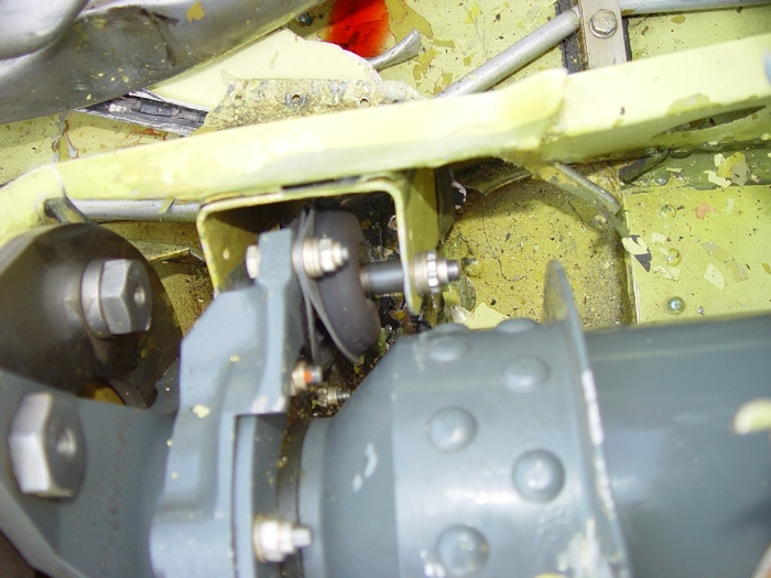
| July 2002: Another view of the damaged flex pack as well as the mounts for the sync shaft hanger bearings. The two black rubber items are the lord mounts. They allow the sync shafts to float forward and aft as the fuselage twists and turns while the aircraft is operated. Click-N-Go Here to view a larger version of this image. |
|
| July 2002: A closer view of the severely damaged flight control tubes. Click-N-Go Here to view a larger version of this image. |
|
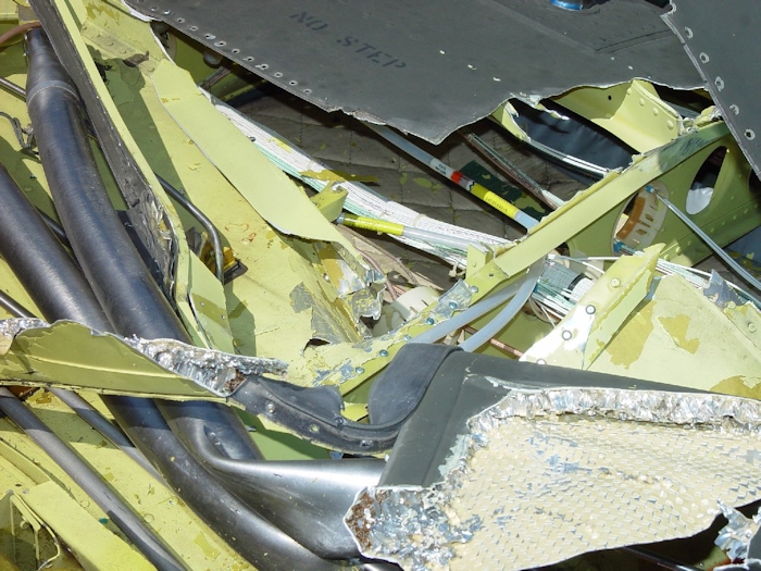
| July 2002: A view looking forward at the damage caused by the blade strike. Click-N-Go Here to view a larger version of this image. |
|
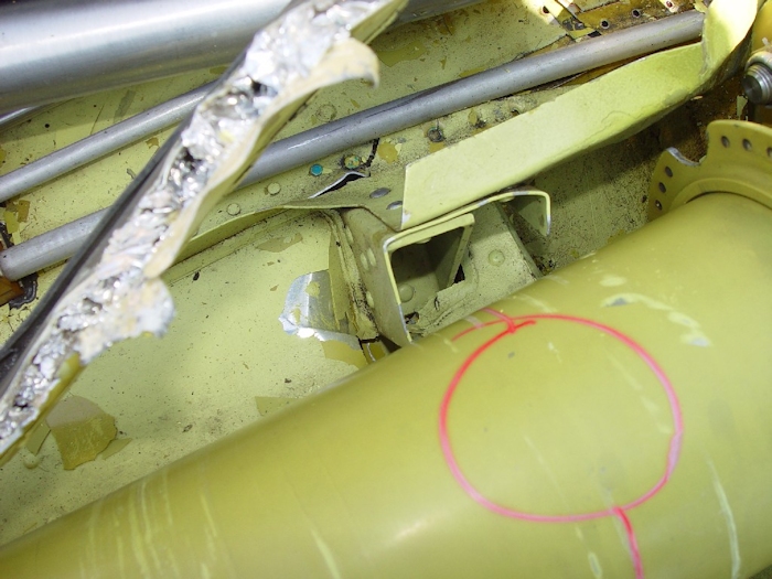
| July 2002: A view of the sheet metal damage just aft of the number two hanger bearing. Click-N-Go Here to view a larger version of this image. |
|
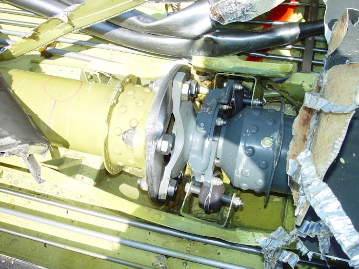
| July 2002: A view of the sheet metal damage to the left (top is left) of the number two hanger bearing. A distorted lord mount is pictured in the center of the image. Click-N-Go Here to view a larger version of this image. |
|
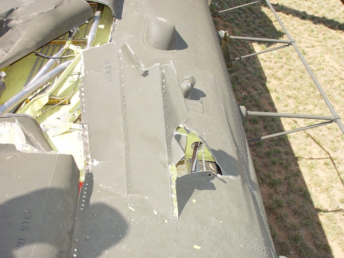
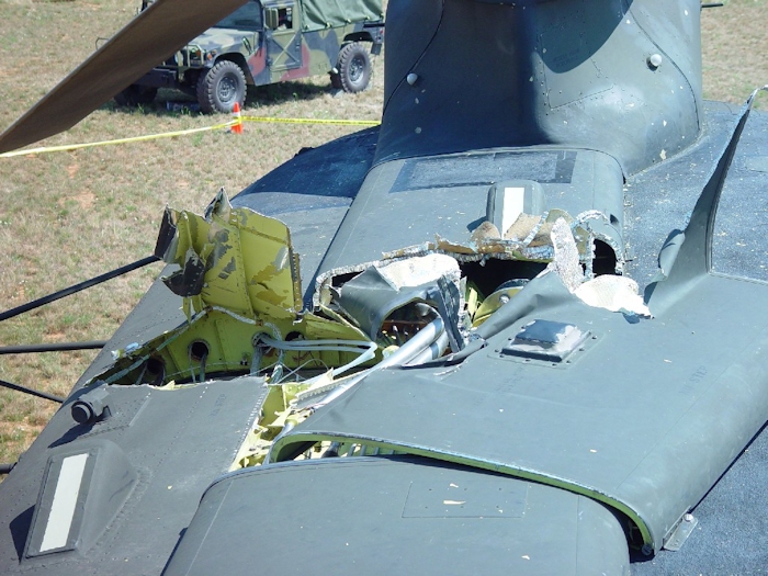
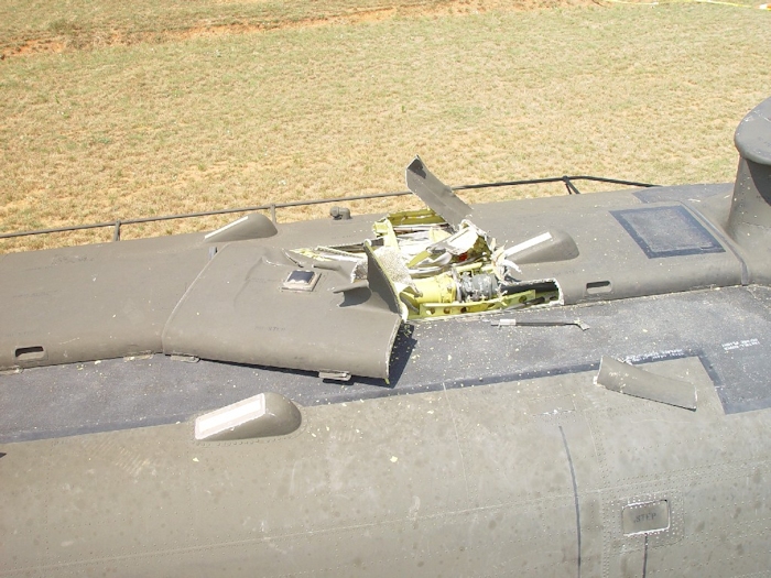
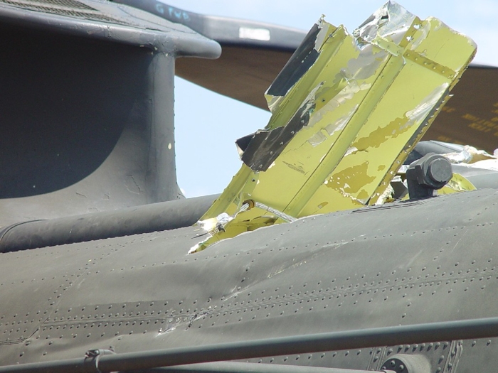
| July 2002: A wider look at the damage to the airframe. The three forward formation lights can be seen. The number one tunnel cover has a single formation light mounted on the top. The number two tunnel cover was displaced and nearly removed from the airframe. Half a tunnel cover support strut can be seen to the right of the tunnel covers as well as debris from the number one tunnel cover just above the forward top step. Click-N-Go Here to view a larger version of this image. |
|
| July 2002: A view down the fuselage looking aft at the tunnel covers. The towel rack looking fixture at the top right of the image is the High Frequency (HF) Radio Antenna. One can also see the aft green rotor blade in contact with the ground. Click-N-Go Here to view a larger version of this image. |
|
| July 2002: A view of the point in which the aft green blade struck the fuselage just above one of the mounts for the HF radio antenna. The fitting to the top right in the image with a cap installed is a vent for the Extended Range Fuel System (ERFS). When that system is installed the cap is removed to allow for the venting of fuel vapors from the internally mounted tanks. There are three of these vents on the CH-47D helicopter. Click-N-Go Here to view a larger version of this image. |
|
| July 2002: A view from the left side of the fuselage showing the damage to the skin and structure during the blade strike. Click-N-Go Here to view a larger version of this image. |
Read more, just Click-N-Go to the next page: 1 2 3 4 5 6 7 8 9 10 |
| Click-N-Go Here to return to the main page for 89-00138. |
| Related Information |
| Explore the Chinook helicopter |
 |
|
| Comments or Questions ? |  |
Email the Webmaster. |
|